
Views: 0 Author: Site Editor Publish Time: 2026-11-05 Origin: Site


The highest barrier to entry in metal manufacturing always comes down to one critical hurdle. You must justify the massive capital expenditure required for initial tooling upfront. Engineers face immense pressure to get these preliminary designs right the very first time. Poorly optimized part geometries quickly lead to premature mold wear and unacceptably high defect rates. They inevitably force engineering teams into expensive, time-consuming tooling revisions just before launch. Every minor geometric oversight amplifies your ongoing manufacturing costs exponentially at scale. Applying rigorous Design for Manufacturability (DFM) principles early prevents this costly rework and dramatically optimizes cycle times. Doing so guarantees a predictable transition from early prototypes into sustainable high-volume production. We will now explore core geometry rules, material impact dynamics, and vendor evaluation strategies to streamline your next major manufacturing initiative.
Consistent wall thickness and appropriate draft angles are the baseline for viable die-casting molds.
Thermal dynamics and metal flow dictate part integrity; strategic use of ribs and radii prevents porosity and structural failure.
Material selection (Aluminum, Zinc, Magnesium) directly impacts the required injection pressure, cycle times, and overall lifespan of die-casting molds.
Selecting a manufacturing partner requires evaluating their in-house tooling capabilities, quality assurance protocols, and revision workflows.
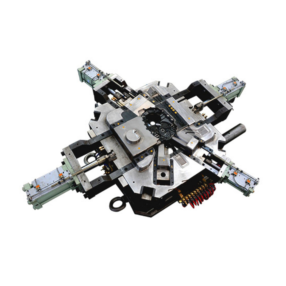
Geometry dictates economics in manufacturing. Complex part shapes dramatically inflate your initial capital expenditure (CapEx). Undercuts and complex parting lines require specialized mechanical mechanisms. Manufacturers use multi-slide molds or side-actions to form these intricate features. These moving components exponentially increase your tooling costs upfront. A simple two-plate tool costs significantly less than a complex multi-slide equivalent. Simpler geometries keep initial tooling budgets highly manageable for your procurement team. Furthermore, mechanical sliders wear out over time. They require precise alignment to prevent flash formation along the parting line.
Cycle time directly drives production profitability. Optimal part design drastically reduces cooling time inside the cavity. Faster cooling allows machine operators to produce more units per hour. This speed directly reduces the per-unit cost at mass scale. Efficient thermal management keeps production running smoothly. Bulky designs trap heat inside the steel core. This trapped heat forces the injection machine to pause. It waits for the thickest metal section to solidify completely. You lose valuable production seconds during every single cycle.
Maintenance frequency dictates overall tool life. Sharp corners and extreme injection pressures accelerate thermal fatigue. This constant fatigue often manifests as severe heat checking on your Die-Casting Molds. Heat checking introduces microscopic cracks onto the tool steel surface. These fine cracks transfer directly onto your cast parts, ruining cosmetic finishes. Designing smoother transitions extends mold longevity drastically. It reduces expensive maintenance downtime. Regular polishing and welding repairs drain your maintenance budget rapidly over high-volume runs.
Engineers must adhere to strict geometric guidelines. You ensure predictable metal flow by following established DFM frameworks. Early compliance prevents severe manufacturing headaches later.
Uniformity remains your most critical baseline parameter. As a standard rule of thumb, maintain consistent thickness across the entire part. This consistency ensures even cooling and fluid metal flow throughout the cavity. Transitions between thick and thin sections cause severe quality problems. They trigger uneven shrinkage during the rapid cooling phase. This localized shrinkage routinely leads to part warping. It also promotes severe internal void formation. Thin sections freeze rapidly inside the cavity. Thick sections remain molten much longer. The freezing metal pulls material from the still-molten areas. This violent pulling action tears the internal microstructure apart.
You must design appropriate draft angles into all vertical walls. They remain entirely necessary for clean part ejection. Proper draft prevents galling across the polished steel surfaces. It completely avoids severely damaging your Die-Casting Molds upon ejection. Industry standards typically recommend 1° to 3° of draft. The exact angle depends heavily on material type. It also relies on the total depth of the mold cavity. Internal walls grip the cooling steel extremely tight. The metal naturally shrinks inward onto internal core pins. Therefore, internal walls require a significantly larger draft angle than external walls.
Never leave sharp 90-degree internal corners in your final CAD file. Generous fillets actively mitigate extreme stress concentrations. They protect both the final cast part and the costly tooling itself. Smooth radii promote much smoother molten metal flow. Liquid metal aggressively attacks sharp steel corners under high pressure. It causes premature erosion and steel washout. Adding radii improves the structural integrity of your product instantly.
Feature | Standard Guideline | Primary Risk of Non-Compliance |
|---|---|---|
Wall Thickness | 1.5mm - 3.0mm (Consistent) | Uneven shrinkage, severe warping, internal voids. |
Draft Angles (External) | 1° - 2° minimum | Part sticking, surface galling, ejector pin marks. |
Draft Angles (Internal) | 2° - 3° minimum | Core pin binding, mold damage during ejection. |
Internal Radii | Min 1.0mm (Match wall thickness) | Stress cracking, turbulent metal flow, die erosion. |
Poor geometry practically guarantees physical defects. You can eliminate most structural failures before cutting any steel. Predictive design adjustments save countless engineering hours and prevent launch delays.
Heavy mass areas trap cooling gases easily. They also suffer from severe localized shrinkage. Gas entrapment causes microscopic voids inside the finished component. Turbulent metal flow literally folds air into the molten mixture. Shrinkage porosity compromises the structural integrity of heavy sections. You should use strategic coring to resolve this specific issue. Coring involves placing permanent steel pins inside the cavity. These pins remove unnecessary mass from thick sections. You save material volume while radically improving part density. You avoid adding solid volume unnecessarily.
You often need extra structural integrity to meet load requirements. Do not achieve this by simply thickening the main walls. Instead, you should add well-designed ribs and bosses. Ribs boost structural rigidity without extending overall cycle times. You must watch your specific geometric limits closely. A rib's thickness should never exceed 70-80% of its adjoining wall thickness. If it grows thicker, you will inevitably see visible sink marks. These depression marks ruin the opposite cosmetic surface completely. Furthermore, you should intersect ribs at staggered angles. Avoid creating massive thermal nodes where multiple heavy ribs cross simultaneously.
Alloy selection changes everything about your specific production environment. Material properties govern thermal dynamics and required machinery. They also determine exactly how long your tooling survives under intense pressure.
Aluminum Alloys (e.g., A380, A360): Aluminum offers incredibly high dimensional stability. It boasts an excellent strength-to-weight ratio for highly demanding structural applications. Engineers widely utilize A380 for complex automotive and aerospace components. However, it significantly impacts your tooling environment. Aluminum requires robust cold-chamber Die Casting processes. The higher melting points subject the steel tooling to extreme thermal stress. This constant thermal shock degrades molds much faster than softer alloys. You must proactively budget for more frequent tool maintenance and replacement.
Zinc Alloys (e.g., Zamak): Zinc delivers truly exceptional ductility and impact resistance. It serves as the absolute ideal choice for intricate, thin-wall designs. Zinc relies entirely on efficient hot-chamber manufacturing processes. Its dramatically lower melting point offers a massive production advantage. This lower operating temperature significantly extends the lifespan of your molds. It fundamentally reduces ongoing tooling maintenance requirements. You can also achieve much tighter mechanical tolerances using standard Zamak alloys.
Magnesium: Magnesium stands as the absolute lightest available structural metal. It also provides excellent machinability for secondary post-processing operations. However, magnesium requires highly specialized handling protocols. You must adjust your tooling parameters carefully. It remains vital to manage its high reactivity and rapid oxidation risks. Magnesium cools incredibly fast inside the mold cavity. It demands ultra-rapid injection speeds to fill complex cavities completely before freezing solid.
You cannot execute a flawless product design without a highly capable vendor. Partner selection absolutely determines your ultimate production success. You must vet their technical capabilities rigorously before issuing purchase orders.
Always assess a vendor's internal tooling infrastructure carefully. Capable partners design, machine, and maintain their molds entirely in-house. They operate their own precision CNC mills and wire EDM machines. This internal capability ensures strict vendor accountability across the board. It also guarantees much faster engineering revision cycles. When tooling breaks or requires adjustments, they fix it immediately on-site. You avoid waiting weeks for an overseas toolmaker to ship replacement parts.
Never skip upfront mold flow analysis. Look for partners actively utilizing advanced computational simulation software. They use it to predict high-risk porosity zones accurately. They optimize exact gate and runner placements digitally. This critical validation happens long before they ever cut expensive tool steel. Simulation completely removes guesswork from the engineering process. It scientifically validates your DFM choices using strict thermodynamic physics.
Verify their physical inspection equipment during your facility audit. Look for automated Coordinate Measuring Machines (CMM) on their factory floor. Demand X-ray inspection capabilities to consistently check for hidden internal voids. Ensure strict adherence to ISO 9001 standards at minimum. Ask about specific aerospace or IATF automotive compliance frameworks if applicable. Robust quality systems actively prevent defective parts from reaching your final assembly line.
Reliable partners operate with total engineering transparency. They provide a highly detailed DFM feedback report alongside their RFQ response. They will proactively highlight potential geometric risks immediately. They locate manufacturing issues hidden deep within your initial CAD files. A trustworthy vendor suggests practical design improvements instantly. They never blindly quote a fundamentally flawed design just to win your initial business.
Successful die casting always demands a delicate engineering balance. You must carefully merge rigid structural integrity requirements with mold-friendly geometry. Overlooking minor design details guarantees major production delays.
Audit your current CAD files to ensure uniform wall thickness and adequate draft angles.
Eliminate sharp internal corners entirely by implementing generous stress-relieving radii.
Optimize your material selection based on target cycle times and expected tooling longevity.
Engage a fully qualified manufacturing partner early for a comprehensive DFM evaluation.
Finalize your 3D models using these rigorous principles today. Securing a professional tooling consultation now prevents incredibly expensive delays tomorrow. Strong geometry builds a highly profitable production foundation.
A: Tooling lifespan varies significantly by the chosen material. Roughly 100,000 shots for Aluminum, up to 1,000,000 shots for Zinc, depending on mold steel quality and maintenance schedules. Proper thermal management and regular preventative maintenance will extend these baseline estimates considerably over time.
A: Yes, but they require sliding cores or secondary machining, which increases the initial cost and complexity of the die-casting molds. Avoid if possible. Every moving slider adds wear points and extends the required cycle time, eating into your profit margins.
A: Typically 1.5mm to 2.0mm for standard aluminum casting, though advanced processes can achieve thinner walls depending on part size and alloy. Pushing limits below this threshold heavily increases the risk of cold shuts and incomplete cavity fills.
A: Prototyping materials behave differently than cast metals. A DFM review is necessary to adjust tolerances, add draft, and optimize for the thermal realities of the die-casting process. You cannot simply use a prototype CAD file for high-pressure production tooling.
