
Views: 0 Author: Site Editor Publish Time: 2026-10-22 Origin: Site


Tooling represents the most significant upfront capital expenditure in any heavy manufacturing project. Miscalculating mold design or material selection quickly leads to thermal fatigue. High scrap rates and costly production delays often follow. You need a reliable framework to evaluate tooling proposals accurately. This guide bridges the gap between component design, manufacturability, and long-term operational efficiency. High-yield production requires aligning mold architecture with projected volumes. It also demands strict adherence to robust engineering principles. Choosing a tooling partner capable of verifiable precision is equally vital. We will explore the core architecture of these complex systems. You will learn how to match mold types to production volumes effectively. We will detail critical design guidelines to ensure optimal yield. By the end, you will understand how to assess tooling quotes based on cycle times and guaranteed longevity.
Optimizing mold components—specifically cooling channels and gating systems—directly dictates cycle times and part consistency.
Selecting the right mold type (single, multi-cavity, or family) depends entirely on an objective ROI analysis of initial CapEx versus projected part volume.
Integrating Design for Manufacturability (DFM) early minimizes porosity, flash, and premature tool wear.
Evaluating a tooling partner requires looking beyond the initial quote to assess their steel selection, heat treatment protocols, and tool life guarantees.
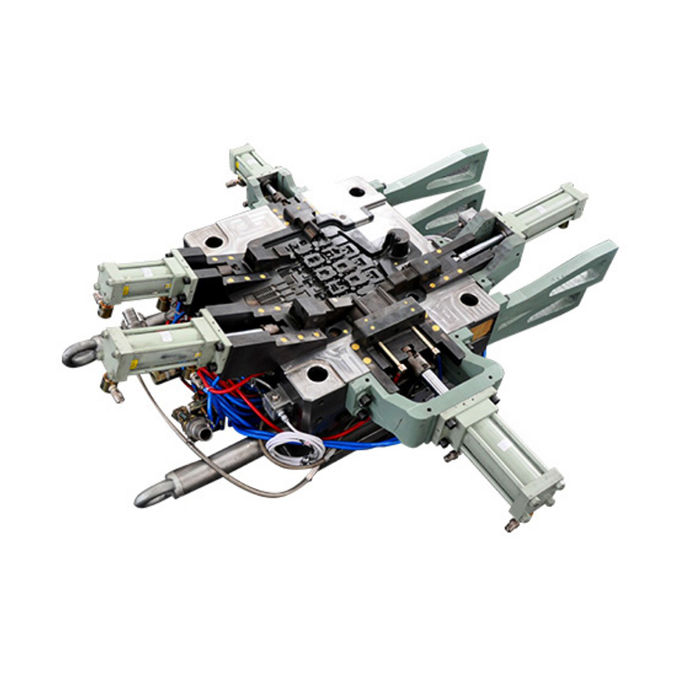
Understanding the anatomy of Die-Casting Molds helps engineers identify potential failure points before they occur. Each sub-system plays a distinct role in cycle time reduction and part quality. If one component fails or underperforms, the entire production run suffers.
These two primary blocks form the foundational architecture. The fixed half mounts stationary to the machine platen. The moving half opens and closes to allow part extraction. Precision alignment between these halves is absolutely critical. If the two sides misalign even slightly, molten metal escapes the cavity. This creates excessive flash along the parting line. Flash requires aggressive post-machining to remove. Secondary machining operations drastically increase your per-part costs. Engineers must scrutinize the alignment locks and guide pins during the design review. A robust alignment system prevents lateral shifting under extreme clamping forces.
The runner system acts as the plumbing network. It controls the flow of molten metal into the main cavity. The gate is the final entry point where metal injects into the part geometry. Poor gating design creates severe implementation risks. If molten metal enters too quickly or at the wrong angle, turbulence occurs. Turbulence leads directly to air entrapment. Trapped air causes internal porosity, weakening the final component. Engineers use fluid dynamics principles to design smooth, tapering runners. Smooth runners maintain metal velocity without causing chaotic flow patterns. An optimized gating system ensures the metal fills the furthest edges of the cavity before solidifying.
Thermal management is arguably the most critical performance metric in die casting. Cooling systems regulate tool temperature during continuous production cycles. Molten aluminum injects at extremely high temperatures. The steel mold must absorb and dissipate this heat rapidly. Efficient thermal management directly dictates your cycle time. Faster cooling means faster part ejection. Furthermore, improper cooling causes severe temperature fluctuations on the steel surface. These fluctuations lead to heat checking, which manifests as fine surface cracks on the tool. Advanced molds utilize conformal cooling channels. These channels follow the complex contours of the part, providing uniform temperature control and extending tool life.
Ejector pins physically push the solidified part out of the moving half. Slides, or core pulls, create complex undercuts or side holes. They allow engineers to design intricate features without trapping the part inside the tool. However, the maintenance reality of these components is demanding. Ejector pins and slides are high-wear moving parts. They endure immense mechanical friction during every single shot. They require strict, documented maintenance schedules. Lack of lubrication causes galling, where the steel surfaces weld together. Seized pins lead to severe part distortion or catastrophic tool failure. You should expect your tooling partner to provide a clear preventative maintenance plan.
Selecting the correct mold classification dictates your initial capital expenditure. It also defines your production ceiling. You must align the tooling architecture directly with your expected market demand.
Engineers use rapid tooling primarily for design validation. Before committing to a high-volume production tool, you need physical parts for testing. Rapid molds allow you to evaluate fit, form, and function. They require a much lower upfront cost compared to production molds. However, you face a significant trade-off regarding tool life. Manufacturers typically cut prototype molds from softer, unhardened steels like P20. These softer metals machine quickly but wear out fast. They cannot withstand the sustained thermal shock of high-pressure injection. Rapid tooling usually degrades after just a few thousand shots.
Single-cavity molds contain only one part geometry per tool. They serve a very specific use case. Engineers deploy them for large, highly complex parts possessing strict tolerance requirements. Think of engine blocks or large structural automotive housings. The evaluation metric here centers on control rather than speed. Production output is inherently slower. However, single-cavity molds offer maximum control over dimensional accuracy. The metal flow and cooling dynamics remain isolated to one part. This isolation reduces the variables causing warpage or shrinkage. If your component demands zero defect tolerance, single-cavity tooling remains the optimal choice.
When producing smaller identical parts, multi-cavity molds dominate the industry. They handle high-volume production seamlessly. A single injection cycle might yield four, eight, or sixteen identical components. This scalability represents their greatest advantage. You pay a higher initial tooling cost for the complex machining. Yet, this investment drastically reduces the piece-price at scale. Multi-cavity molds demand exceptional engineering rigor. They require highly balanced runner systems. If the runners are unbalanced, cavities fill at different rates. Uneven filling causes some parts to flash while others suffer from cold shuts.
Family molds produce different components for the same assembly simultaneously. For instance, a single mold might cast both the left and right halves of a motor enclosure. The primary use case is inventory balance. You always produce a complete set of matching parts per cycle. Despite this convenience, the implementation risk remains exceptionally high. Different part geometries have different volumes and wall thicknesses. They are highly susceptible to uneven filling and differential shrinkage. Producing a successful family mold requires advanced flow simulation during the design phase. You must ensure the runner system artificially balances the metal flow to fill unequal cavities at the exact same moment.
Mold Classification |
Primary Use Case |
Initial CapEx |
Expected Tool Life (Shots) |
|---|---|---|---|
Rapid Tooling |
Design validation, functional testing |
Low |
1,000 - 5,000 |
Single-Cavity |
Large, complex, high-tolerance parts |
Moderate to High |
50,000 - 100,000+ |
Multi-Cavity |
High-volume small identical components |
High |
50,000 - 100,000+ |
Family Mold |
Matching sets for complete assemblies |
High |
50,000 - 100,000+ |
Implementing DFM principles early in the product lifecycle prevents expensive tooling revisions later. Proper part design heavily influences mold longevity. Poor design forces the tooling to work harder, accelerating wear and increasing scrap rates. Engaging in comprehensive Die Casting design reviews ensures a smooth transition to mass production.
The foremost guideline is to keep walls as consistent as possible throughout the part. Thick sections take significantly longer to cool than thin sections. This temperature disparity creates differential cooling. When parts cool unevenly, the resulting internal stresses cause severe warping. Furthermore, thick sections often solidify last. The metal shrinks as it cools, pulling material away from the center. This creates internal voids known as shrink porosity. If a design requires varying thicknesses, you must incorporate gradual transitions. Avoid abrupt steps between thick and thin walls.
Draft refers to the slight taper applied to vertical walls parallel to the tool's opening direction. You must standardize minimum draft angles across the part design. Typically, engineers apply 1° to 3° of draft, depending on the hole depth and the specific alloy. Aluminum shrinks tightly onto the steel cores as it solidifies. Without sufficient draft, the part grips the mold. The ejector pins must then apply immense force to push the part out. Proper draft ensures smooth ejection. This simple guideline reduces tool wear, prevents galling on the core pins, and stops part distortion during removal.
You should completely eliminate sharp internal corners from your geometry. Sharp corners act as severe stress concentrators. During injection, molten metal slams into these corners, eroding the steel prematurely. As the part cools and shrinks around a sharp corner, it often cracks. Adding generous radii and fillets smooths the metal flow. It allows the material to transition around corners without turbulence. It also reduces thermal stress in the mold steel itself, effectively mitigating premature heat checking and cracking.
While casting achieves excellent near-net shapes, certain features demand tighter tolerances. You must leave predictable material for secondary CNC operations. Design the mold to hit standard casting tolerances. Use frameworks like NADCA (North American Die Casting Association) standards as a baseline. For critical mating surfaces or bearing bores, add a specific machining allowance. Do not add too much material. Excessive material forces the CNC machine to cut through the dense outer "skin" of the casting into the potentially porous center. A standard allowance of 0.5mm to 1.0mm is usually sufficient for precision finishing.
Creating a high-performance tool is a highly specialized engineering endeavor. Procurement teams must track specific milestones to ensure quality. Skipping any of these steps inevitably leads to inferior tooling.
Mold Flow Simulation & Engineering: Your partner must utilize advanced software like MAGMASOFT. This software predicts flow vectors, cooling rates, and potential defect zones. Engineers must simulate the injection cycle digitally prior to cutting any steel. This uncovers air traps and shrinkage issues before they become permanent physical problems.
Material Selection & Tool Steel: The foundation of tool life is the steel grade. Premium H13 or equivalent hot-work tool steels are non-negotiable. These alloys possess exceptional red hardness. They maintain their structural integrity even when continuously exposed to high-pressure aluminum and zinc alloys.
CNC Machining & EDM (Electrical Discharge Machining): Look for suppliers utilizing high-speed, multi-axis milling centers. The fixed and moving halves require extreme precision. For sharp internal corners or deep ribs, manufacturers use wire and sinker EDM. EDM achieves micro-tolerances that traditional drill bits simply cannot reach.
Heat Treatment & Surface Engineering: Raw H13 steel is too soft for production. Proper hardening and tempering processes alter the crystalline structure of the metal. This thermal processing maximizes longevity. Manufacturers often apply surface coatings like PVD (Physical Vapor Deposition) to critical wear areas. These treatments help the mold withstand thermal shock and aggressive molten alloys.
T1 Trials (First Article Inspection): The T1 milestone represents the first physical test of the mold. The manufacturer injects metal and evaluates the resulting parts. Do not accept a mold until T1 samples pass rigorous dimensional and metallurgical testing. Expect to see minor flash or dimensional deviations at this stage. The tooling partner will then make necessary micro-adjustments to the steel.
Choosing the lowest bidder often results in disastrous long-term outcomes. You must evaluate tooling quotes based on production efficiency and engineering reliability. A cheap mold usually hides inferior steel or neglected cooling designs.
Consider the daily operational impact of the tool design. A cheaper mold might utilize a simplistic cooling system. This simplistic design increases your cycle time by 5 seconds per shot. Over a 100,000-part run, those extra seconds translate into hundreds of hours of wasted machine time. That wasted time drastically inflates your piece price. Always evaluate quotes based on guaranteed cycle times. An upfront investment in conformal cooling or premium gating design pays massive dividends through accelerated, stable production.
A mold is a depreciating asset. You need to know exactly how long it will last before requiring major refurbishment. Standard aluminum molds should yield 50,000 to 100,000+ shots depending on part complexity. Zinc molds typically last significantly longer due to lower injection temperatures. Ensure your tooling partner specifies tool life guarantees in the contract. Discuss maintenance responsibilities clearly. Clarify who bears the cost of replacing worn ejector pins or damaged core slides during the guaranteed lifespan.
You need verifiable proof of a supplier's capabilities. Take these actionable steps when auditing a new partner:
Request documentation of their steel supply chain. This protects you from low-grade, counterfeit substitute steels that crack early in production.
Evaluate their in-house maintenance and repair capabilities. When a slide seizes, you need a partner who can fix it immediately without outsourcing.
Verify compliance with recognized quality standards. Look for ISO 9001 certifications. If you operate in specialized sectors, demand automotive (IATF 16949) or aerospace credentials.
Successful part production relies entirely on treating the mold as an engineered asset, not a commodity purchase. The tooling architecture defines your upper limit for quality and speed. Balancing DFM principles, strategic mold type selection, and rigorous supplier vetting is the only proven path to scalable, defect-free production. Never compromise on tool steel quality or thermal management design. Minor upfront savings always result in massive downstream production delays. We strongly recommend engaging with tooling engineers during the early CAD stages. Submit your CAD files for a comprehensive DFM review. Contact our engineering team today to develop a customized tooling strategy and receive an accurate RFQ based on guaranteed cycle times.
A: Realistic lead times typically range from 4 to 12 weeks. The timeline depends heavily on part complexity, the number of cavities, and the required DFM iterations. Advanced flow simulations and rigorous heat treatment protocols add time but guarantee a superior final tool.
A: Lifespan varies based on the alloy and maintenance. Zinc molds endure lower temperatures and often last over 500,000 shots. Aluminum molds experience intense thermal shock, typically lasting between 50,000 and 100,000 shots. Premium tool steel quality and strict preventative maintenance schedules drastically extend these lifespans.
A: Yes, but with limitations. Engineers utilize "steel safe" design principles. It is much easier to machine steel away from the mold (adding volume to the part) than to weld steel back in. Major geometry changes often require costly inserts or entirely new tool blocks.
A: H13 is a hot-work tool steel renowned for its superior red hardness. It retains its structural strength and resists thermal fatigue even during continuous exposure to extreme temperatures. This unique metallurgical profile prevents the tool from cracking under high-pressure injection cycles.
